Development of a 3D-Printed BLDC Motor & Controller
This project presents a 3D-printed BLDC motor with a hollow-shaft rotor and a nickel-reinforced stator, paired with a custom motor controller supporting Hall sensors, a BiSS-C absolute encoder, and CAN communication. Experiments show accurate step-tracking with short settling time and negligible steady-state error, demonstrating feasibility for robotic and precision applications.
Step response test
Key Innovations
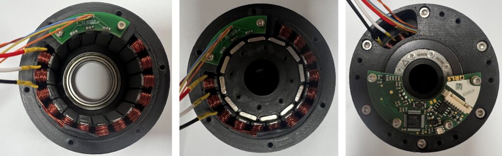
Hollow-Shaft Rotor: 12-pole NdFeB magnets arranged on a 3D-printed rotor with a 15 mm through-bore for cables/shafts, reducing inertia while maintaining torque density.
Nickel-Reinforced Stator: 18-slot stator with internal cavities accepting stacked 0.1 mm nickel plates to boost flux density and mitigate eddy currents; coils wound with 0.5 mm wire in Y-connection.
Integrated Sensing: Three A3144 Hall switches spaced for 120° electrical separation (20° mechanical for a 12-pole rotor) plus a Renishaw BiSS-C absolute encoder (19-bit single-turn, 16-bit multi-turn).
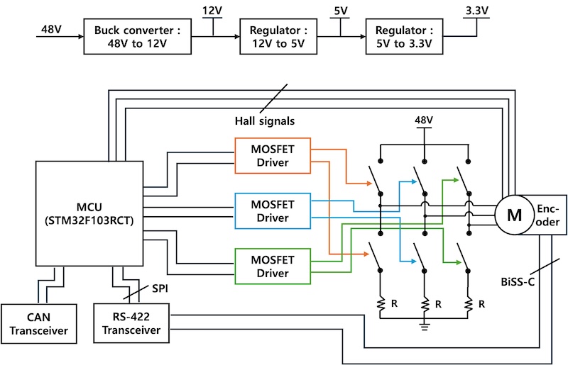
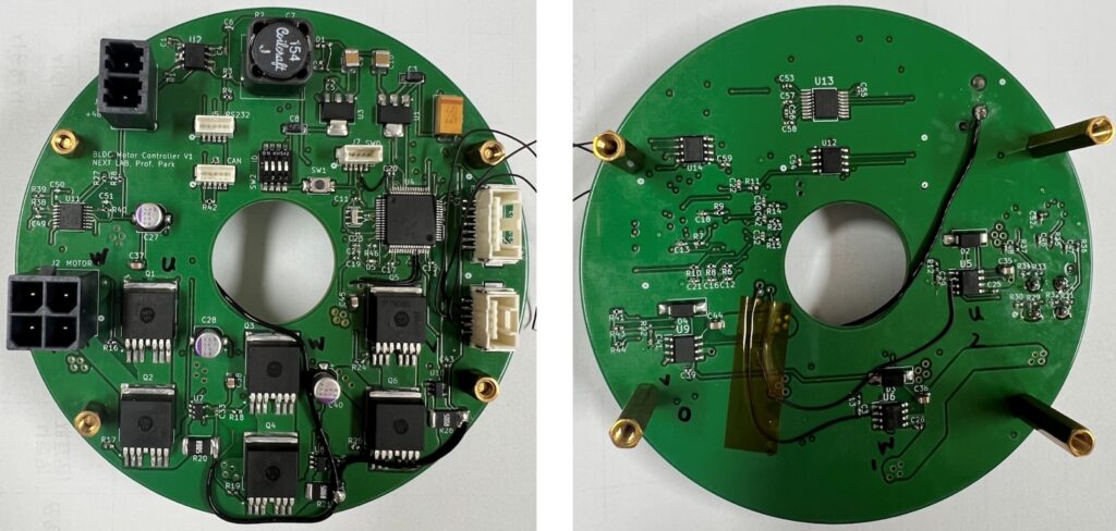
Custom Controller: Cascaded buck supplies (48→12→5→3.3 V with LM5169), IRS2184 half-bridge gate drivers, low-side current sensing via INA180A1, BiSS-C over RS-422, and CAN to the host. PID position control at 1 kHz.
Experimental Validation
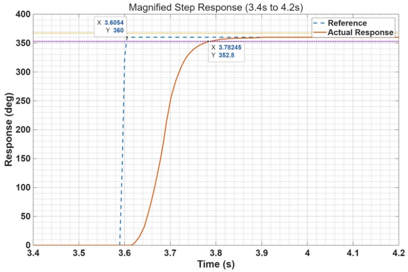
Step Response (0°→360°→0°): Settling time ≈ 0.18 s (±2%), steady-state error ≈ 0.029°.
Comparison: A Kollmorgen frameless BLDC actuator (with reducer) settles ≈0.048 s in a 30° test—faster, but the printed prototype emphasizes cost and customization benefits for research and rapid iteration.